DIY Sliding Gate Controller
How I built a gate controller using a Raspberry Pi and some relays.
11 minute read · 2142 words
Recently, the driveway gate stopped working. It would open but not close. First thought was that it was a faulty motor, so I took a picture of the wiring so I could easily replace the motor. Then I attempted to press the remote button to close the gate, and... it still wouldn't close, so that means the control board WAS the problem, great! Likely some kind of fuse or relay, but I wasn't sure.
I opened up the box to the control board and looked at the circuit board. I checked the fuses, everything was fine. So I started looking at the board to see if I could find any obvious signs of damage, like burnt components or broken traces, but I didn't see anything. So I needed to replace the control board. Looking online, I couldn't find the same board, and any similar boards ranged between $230 and $500 USD. But that's quite expensive.
I did see a 6x2 Molex connector with some wires coming in from outside. Based on the picture I took earlier and wire colors, I traced the motor wires and used a multimeter to test the voltage across the different pins, and found out that there is incoming 120v AC power, and the circuit was simply switching the power to the motor to open or close the gate with a ground. So I decided to test the motor directly by bypassing the control board, just to make sure that it was working. I got a computer power cable (C13 connector) and a previously cut C14 to C13 extension cord, and I was able to make the motor run by taking the exposed hot/live wire and touching it to the previously identified wires from the motor. Suprise suprise, The motor ran perfectly fine. So that confirmed it. It was the board.
So I started looking into alternatives, and thought why not build my own gate controller? I have a un-used Raspberry Pi 3 Model B+ and a RPi Relay Board from WaveShare. I knew I could use the relay board to switch the 120v AC power. The motor itself had three wires, one for opening, one for closing, and a common/ground wire, and I had 3 relays. The idea was to use one relay for opening, one for closing, and the last one as a safety mechanism to cut power to the motor when not in use.
With the DIY raspberry pi idea, I started to stick some breadboard wires onto the GPIO pins. Then wrote a simple Python script using the RPi.GPIO library to control the relays. I tested to see if I could make the relays switch on and off, and it worked! I was able to control the relays using my Raspberry Pi.
Next, I had to figure out how to add a triggering mechanism, as I didn't wanna be fully reliant on some Flask web server. So I went back and opened up the gate controller and looked at the circuit board. I was hoping to find some kind of input that I could use to trigger the relays, I noticed that there was two wires that went into the controller. So I measured the voltage across those wires and found that it was 5v when the remote button was not pressed, and it dropped to ground (0v) when the button was pressed. That was perfect! I could use that as a signal to trigger the relays.
I then went back to my python code and added code for a "trigger" GPIO pin. I set it as a input pin using internal pull-up. Then I added a loop that would check the state of the trigger pin, and if it detected a voltage change (1V -> 0V), it would activate the relays to open or close the gate. Once I had that working, I remembered there was also a safety signal that would stop and reverse the gate if it detected an obstacle. I wanted to integrate that as well, so I added another input pin for the safety signal. If the safety signal was triggered, it would immediately turn off the relays thus stopping the gate.
I also knew that the gate took approximately 12 seconds to fully open or close, so I added a timer to the code that would automatically turn off the relays after 12 seconds to prevent any potential damage to the motor from trying to move when it could not.
Based on what I described above, although this version was purely a proof of concept (PoC) and didn't actually have anything plugged into the relays. It was a good starting point for me to prove that I could do this and I could spend more time on this. Here is the full code for the gate controller that I had at this point:
import RPi.GPIO as GPIO
import time

# ---------- CONFIG ----------
TRIGGER_PIN = 16  # white
CLOSED_LIMIT_PIN = 12  # blue
OPEN_LIMIT_PIN = 6  # orange
SAFETY_PIN = 18  # yellow

RELAY_OPEN_PIN = 20
RELAY_CLOSE_PIN = 21

MAX_RUNTIME = 12
# ----------------------------

GPIO.setmode(GPIO.BCM)

GPIO.setup(TRIGGER_PIN, GPIO.IN, pull_up_down=GPIO.PUD_UP)
GPIO.setup(CLOSED_LIMIT_PIN, GPIO.IN, pull_up_down=GPIO.PUD_UP)
GPIO.setup(OPEN_LIMIT_PIN, GPIO.IN, pull_up_down=GPIO.PUD_UP)
GPIO.setup(SAFETY_PIN, GPIO.IN, pull_up_down=GPIO.PUD_UP)

GPIO.setup(RELAY_OPEN_PIN, GPIO.OUT, initial=GPIO.HIGH)
GPIO.setup(RELAY_CLOSE_PIN, GPIO.OUT, initial=GPIO.HIGH)

def relay_on(pin):
  GPIO.output(pin, GPIO.LOW)

def relay_off(pin):
  GPIO.output(pin, GPIO.HIGH)


def stop_all():
  relay_off(RELAY_OPEN_PIN)
  relay_off(RELAY_CLOSE_PIN)

def safety_active():
  return GPIO.input(SAFETY_PIN) == GPIO.LOW

def closed_limit():
  return GPIO.input(CLOSED_LIMIT_PIN) == GPIO.LOW

def open_limit():
  return GPIO.input(OPEN_LIMIT_PIN) == GPIO.LOW

def decide_direction():
  if open_limit():
    print("Gate open → closing")
    return "close"

  if closed_limit():
    print("Gate closed → opening")
  else:
    print("Unknown position → default opening")

  return "open"


try:
  while True:
    if GPIO.input(TRIGGER_PIN) == GPIO.LOW:
      print("Trigger detected")
      direction = decide_direction()
      start_time = time.time()

      if direction == "open":
        relay_on(RELAY_OPEN_PIN)
        relay_off(RELAY_CLOSE_PIN)

      if direction == "close":
        relay_on(RELAY_CLOSE_PIN)
        relay_off(RELAY_OPEN_PIN)

      while True:
        if safety_active():
          print("SAFETY ACTIVE - STOP")
          break

        elapsed = time.time() - start_time
        if elapsed > MAX_RUNTIME:
          print("Timeout reached")
          break

        if direction == "open" and open_limit():
          print("Open limit reached")
          break

        if direction == "close" and closed_limit():
          print("Closed limit reached")
          break

        time.sleep(0.01)

      stop_all()

      while GPIO.input(TRIGGER_PIN) == GPIO.LOW:
          time.sleep(0.05)

    time.sleep(0.05)

except KeyboardInterrupt:
  pass

finally:
  stop_all()
  GPIO.cleanup()
Now that I had a working PoC. I sent it to a Large Language Model (LLM) and asked it to review the code and give me some suggestions, plus for it to implement a flask web server and design a simple web interface to visualize the state of the gate. I know, I know, I could have done it myself, but with everyone "vibe-coding" these days, I wanted to see how well it could do. So here's the code that it came up with:
import RPi.GPIO as GPIO
import time
import threading
from flask import Flask, render_template_string

# ---------- CONFIG ----------
TRIGGER_PIN = 16
CLOSED_LIMIT_PIN = 12
OPEN_LIMIT_PIN = 6
SAFETY_PIN = 18

RELAY_OPEN_PIN = 20
RELAY_CLOSE_PIN = 21

MAX_RUNTIME = 12
# ----------------------------

GPIO.setmode(GPIO.BCM)

GPIO.setup(TRIGGER_PIN, GPIO.IN, pull_up_down=GPIO.PUD_UP)
GPIO.setup(CLOSED_LIMIT_PIN, GPIO.IN, pull_up_down=GPIO.PUD_UP)
GPIO.setup(OPEN_LIMIT_PIN, GPIO.IN, pull_up_down=GPIO.PUD_UP)
GPIO.setup(SAFETY_PIN, GPIO.IN, pull_up_down=GPIO.PUD_UP)

GPIO.setup(RELAY_OPEN_PIN, GPIO.OUT, initial=GPIO.HIGH)
GPIO.setup(RELAY_CLOSE_PIN, GPIO.OUT, initial=GPIO.HIGH)


# ---------- STATE ----------
status_msg = "Idle"
direction = "None"
runtime = 0


# ---------- GPIO HELPERS ----------
def relay_on(pin):
    GPIO.output(pin, GPIO.LOW)


def relay_off(pin):
    GPIO.output(pin, GPIO.HIGH)


def stop_all():
    relay_off(RELAY_OPEN_PIN)
    relay_off(RELAY_CLOSE_PIN)


def safety_active():
    return GPIO.input(SAFETY_PIN) == GPIO.LOW


def closed_limit():
    return GPIO.input(CLOSED_LIMIT_PIN) == GPIO.LOW


def open_limit():
    return GPIO.input(OPEN_LIMIT_PIN) == GPIO.LOW


def decide_direction():
    if closed_limit():
        return "OPEN"

    if open_limit():
        return "CLOSE"

    return "OPEN"


# ---------- CONTROL LOOP ----------
def control_loop():
    global status_msg, direction, runtime

    while True:

        if GPIO.input(TRIGGER_PIN) == GPIO.LOW:

            status_msg = "Trigger detected"

            dir_cmd = decide_direction()
            direction = dir_cmd

            start_time = time.time()

            # Start motion
            if dir_cmd == "OPEN":
                relay_on(RELAY_OPEN_PIN)
                relay_off(RELAY_CLOSE_PIN)

            if dir_cmd == "CLOSE":
                relay_on(RELAY_CLOSE_PIN)
                relay_off(RELAY_OPEN_PIN)

            status_msg = f"Moving {dir_cmd}"

            while True:

                runtime = round(time.time() - start_time, 2)

                if safety_active():
                    status_msg = "SAFETY ACTIVE — STOP"
                    break

                if runtime > MAX_RUNTIME:
                    status_msg = "Timeout"
                    break

                if dir_cmd == "OPEN" and open_limit():
                    status_msg = "Open limit reached"
                    break

                if dir_cmd == "CLOSE" and closed_limit():
                    status_msg = "Closed limit reached"
                    break

                time.sleep(0.01)

            stop_all()
            runtime = 0
            direction = "None"
            status_msg = "Stopped"

            while GPIO.input(TRIGGER_PIN) == GPIO.LOW:
                time.sleep(0.05)

        time.sleep(0.05)


# ---------- FLASK ----------
app = Flask(__name__)

HTML = """
<!doctype html>
<html>
<head>
<title>Gate Controller</title>
<style>
body { font-family: Arial; text-align:center; }
.box { display:inline-block; padding:20px; margin:10px; border-radius:10px; width:140px; }
.on { background:#4CAF50; color:white; }
.off { background:#ccc; }
h1 { margin-top:30px; }
</style>
</head>
<body>

<h1>Gate Controller Visualizer</h1>

<h2>Status: {{status}}</h2>
<h3>Direction: {{direction}}</h3>
<h3>Runtime: {{runtime}} s</h3>

<div>
<div class="box {{trigger}}">Trigger</div>
<div class="box {{closed}}">Closed Limit</div>
<div class="box {{open}}">Open Limit</div>
<div class="box {{safety}}">Safety</div>
</div>

<div>
<div class="box {{relay_open}}">Relay OPEN</div>
<div class="box {{relay_close}}">Relay CLOSE</div>
</div>

<script>
setTimeout(function(){
   window.location.reload(1);
}, 1000);
</script>

</body>
</html>
"""


def state_class(active):
    return "on" if active else "off"


@app.route("/")
def index():

    return render_template_string(
        HTML,
        status=status_msg,
        direction=direction,
        runtime=runtime,
        trigger=state_class(GPIO.input(TRIGGER_PIN) == GPIO.LOW),
        closed=state_class(closed_limit()),
        open=state_class(open_limit()),
        safety=state_class(safety_active()),
        relay_open=state_class(GPIO.input(RELAY_OPEN_PIN) == GPIO.LOW),
        relay_close=state_class(GPIO.input(RELAY_CLOSE_PIN) == GPIO.LOW),
    )


# ---------- MAIN ----------
if __name__ == "__main__":

    thread = threading.Thread(target=control_loop, daemon=True)
    thread.start()

    try:
        app.run(host="0.0.0.0", port=5000)
    finally:
        stop_all()
        GPIO.cleanup()
Although that was nice, I didn't want to rely on a web server to control the gate, and I wanted to be able to control it from my phone, and not just the 400Mhz remotes. I didn't want to have to press the physical trigger button every time I wanted to open or close the gate.
Home Assistant
I already had a Home Assistant instance setup, so I figured I could integrate the gate controller with it. I could have just used the Flask web server and made some HTTP requests to it from Home Assistant, but that felt a bit hacky to me. I wanted to have a more direct integration, where Home Assistant could directly trigger the relays without having to go through a web server, and for it to be able to read the state of the gate as well.
But I didn't know how to do that, I had some experience with ESPHome and even contributed some configurations. But outside of that I had never communicated to Home Assistant via a Raspberry Pi before. I wasn't sure what I could use to communicate between the two devices. I knew that Home Assistant supported a lot of different protocols and integrations, but I wasn't sure which one would be the best fit for my use case. I knew that it was possible to do something, as there were projects online of people using Raspberry Pis and Home Assistant together, the best example being the Magic Mirror project which used a Raspberry Pi to run a smart mirror interface that integrated with Home Assistant. That led me down a path and found out that people had used the MQTT integration. So I figured I could use MQTT too.
I found a Python MQTT library that seemed to be work well enough for my needs. I looked into the MQTT integration page and saw it had a discovery feature that would automatically discover new devices that were added to the MQTT broker, so I decided to use that. I modified my existing code to publish the state of the gate to the MQTT broker, and to subscribe to a topic that would allow me to trigger the gate from Home Assistant. It took quite a bit of trial and error to get it working but it was a fun learning experience. I did have one more requirement, which was to make MQTT optional, as I still wanted the gate to be able to function without it, and not have it be a hard dependency. So I added some configuration options to enable or disable MQTT, and to specify the MQTT broker details. Here's a snippet of the code that I ended up with:
import paho.mqtt.client as mqtt
import gpio_control as gpio # This contains the GPIO control code from before, just abstracted away into a separate module

availability_topic = f"{BASE_TOPIC}/availability"
command_topic = f"{BASE_TOPIC}/command"
restart_topic = f"{BASE_TOPIC}/restart/set"
mode_command_topic = f"{BASE_TOPIC}/mode/set"
state_topic = f"{BASE_TOPIC}/state"
position_topic = f"{BASE_TOPIC}/position"

mqtt_started = False
_client: mqtt.Client | None = None

_on_command_cb = None  # function(payload: str) -> None

def set_command_handler(fn):
    global _on_command_cb
    _on_command_cb = fn

def _make_client() -> mqtt.Client:
    # paho-mqtt 2.x compatibility with old callbacks
    c = mqtt.Client(
        client_id=DEVICE_ID,
        clean_session=True,
    )
    return c

def mqtt_publish(topic: str, payload, retain: bool = False, qos: int = 0) -> None:
    if not MQTT_ENABLED or _client is None:
        return
    try:
        _client.publish(topic, payload, retain=retain, qos=qos)
    except Exception:
        pass

def build_state_dict(state: dict[str, str | bool | float]) -> dict[str, str | bool | float]:
    """
    state is a dict from app.py containing:
      status, direction, runtime, position
      plus: maintenance (bool), motor_enabled (bool)
    """
    # Derive hard-end positions from limit switches when present
    if gpio.closed_limit():
        pos = "closed"
    elif gpio.open_limit():
        pos = "open"
    else:
        pos = state.get("position", "stopped")

    return {
        "status": state.get("status", ""),
        "direction": state.get("direction", "none"),
        "runtime": round(float(state.get("runtime", 0.0)), 2),
        "safety": bool(gpio.safety_active()),
        "trigger": bool(gpio.trigger_active()),
        "closed_limit": bool(gpio.closed_limit()),
        "open_limit": bool(gpio.open_limit()),
        "relay_open": bool(gpio.relay_open_active()),
        "relay_close": bool(gpio.relay_close_active()),
        "relay_common": bool(gpio.relay_common_active()),
        "position": pos,
        "mode": state.get("mode", "auto"),
    }

def publish_device_discovery() -> None:
    payload = {
        "dev": {
            "ids": DEVICE_ID,
            "name": FRIENDLY_NAME,
            "mf": MANUFACTURER,
            "mdl": MODEL,
            "sw": SW_VERSION,
            "sn": DEVICE_ID,
            "hw": HW_VERSION,
        },
        "o": {"name": ORIGIN_NAME, "sw": ORIGIN_SW, "url": ORIGIN_URL},
        "state_topic": state_topic,
        "qos": 0,
        "cmps": {
            # Primary Entity
            "gate_cover": {
                "p": "cover",
                "name": FRIENDLY_NAME,
                "unique_id": f"{DEVICE_ID}_cover",
                "command_topic": command_topic,
                "state_topic": position_topic,
                "payload_open": "OPEN",
                "payload_close": "CLOSE",
                "payload_stop": "STOP",
                "payload_force_open": "OPEN_FORCE",
                "state_open": "open",
                "state_closed": "closed",
                "state_opening": "opening",
                "state_closing": "closing",
                "state_stopped": "stopped",
                "state_none": "stopped",
                "availability_topic": availability_topic,
                "optimistic": False,
            },

            # Diagnostic Sensors
            "safety": {
                "p": "binary_sensor",
                "name": f"{FRIENDLY_NAME} Safety",
                "unique_id": f"{DEVICE_ID}_safety",
                "device_class": "safety",
                "state_topic": state_topic,
                "value_template": "{{ 'ON' if value_json.safety else 'OFF' }}",
                "payload_on": "ON",
                "payload_off": "OFF",
                "availability_topic": availability_topic,
            },
            "runtime": {
                "p": "sensor",
                "name": f"{FRIENDLY_NAME} Runtime",
                "unique_id": f"{DEVICE_ID}_runtime",
                "unit_of_measurement": "s",
                "state_topic": state_topic,
                "value_template": "{{ value_json.runtime }}",
                "availability_topic": availability_topic,
            },
            "direction": {
                "p": "sensor",
                "name": f"{FRIENDLY_NAME} Direction",
                "unique_id": f"{DEVICE_ID}_direction",
                "state_topic": state_topic,
                "value_template": "{{ value_json.direction }}",
                "availability_topic": availability_topic,
            },
            "status": {
                "p": "sensor",
                "name": f"{FRIENDLY_NAME} Status",
                "unique_id": f"{DEVICE_ID}_status",
                "state_topic": state_topic,
                "value_template": "{{ value_json.status }}",
                "availability_topic": availability_topic,
            },

            # Manual Control Buttons
            "open_btn": {
                "p": "button",
                "name": f"{FRIENDLY_NAME} Open",
                "unique_id": f"{DEVICE_ID}_open_btn",
                "command_topic": command_topic,
                "payload_press": "OPEN",
                "availability_topic": availability_topic,
            },
            "close_btn": {
                "p": "button",
                "name": f"{FRIENDLY_NAME} Close",
                "unique_id": f"{DEVICE_ID}_close_btn",
                "command_topic": command_topic,
                "payload_press": "CLOSE",
                "availability_topic": availability_topic,
            },
            "stop_btn": {
                "p": "button",
                "name": f"{FRIENDLY_NAME} Stop",
                "unique_id": f"{DEVICE_ID}_stop_btn",
                "command_topic": command_topic,
                "payload_press": "STOP",
                "availability_topic": availability_topic,
            },

            # Limit Switches
            "open_limit": {
                "p": "binary_sensor",
                "name": f"{FRIENDLY_NAME} Open Limit",
                "unique_id": f"{DEVICE_ID}_open_limit",
                "device_class": "opening",
                "state_topic": state_topic,
                "value_template": "{{ 'ON' if value_json.open_limit else 'OFF' }}",
                "availability_topic": availability_topic,
            },
            "closed_limit": {
                "p": "binary_sensor",
                "name": f"{FRIENDLY_NAME} Closed Limit",
                "unique_id": f"{DEVICE_ID}_closed_limit",
                "device_class": "opening",
                "state_topic": state_topic,
                "value_template": "{{ 'ON' if value_json.closed_limit else 'OFF' }}",
                "availability_topic": availability_topic,
            },
            "trigger_input": {
                "p": "binary_sensor",
                "name": f"{FRIENDLY_NAME} Trigger",
                "unique_id": f"{DEVICE_ID}_trigger",
                # "device_class": "occupancy",
                "state_topic": state_topic,
                "value_template": "{{ 'ON' if value_json.trigger else 'OFF' }}",
                "entity_category": "diagnostic",
                "availability_topic": availability_topic,
            },

            # Relay Controls
            "relay_open": {
                "p": "switch",
                "name": f"{FRIENDLY_NAME} Relay Open",
                "unique_id": f"{DEVICE_ID}_relay_open",
                "command_topic": command_topic,
                "state_topic": state_topic,
                "value_template": "{{ 'ON' if value_json.relay_open else 'OFF' }}",
                "payload_on": "RELAY_OPEN_ON",
                "payload_off": "RELAY_OPEN_OFF",
                "entity_category": "config",
                "availability_topic": availability_topic,
            },
            "relay_close": {
                "p": "switch",
                "name": f"{FRIENDLY_NAME} Relay Close",
                "unique_id": f"{DEVICE_ID}_relay_close",
                "command_topic": command_topic,
                "state_topic": state_topic,
                "value_template": "{{ 'ON' if value_json.relay_close else 'OFF' }}",
                "payload_on": "RELAY_CLOSE_ON",
                "payload_off": "RELAY_CLOSE_OFF",
                "entity_category": "config",
                "availability_topic": availability_topic,
            },
            "relay_common": {
                "p": "switch",
                "name": f"{FRIENDLY_NAME} Motor Enable",
                "unique_id": f"{DEVICE_ID}_relay_common",
                "command_topic": command_topic,
                "state_topic": state_topic,
                "value_template": "{{ 'ON' if value_json.motor_enabled else 'OFF' }}",
                "payload_on": "RELAY_COMMON_ON",
                "payload_off": "RELAY_COMMON_OFF",
                "entity_category": "config",
                "icon": "mdi:engine",
                "availability_topic": availability_topic,
            },
        },
    }

    mqtt_publish(
        f"homeassistant/device/{DEVICE_ID}/config",
        json.dumps(payload),
        retain=True,
        qos=1,
    )

def _on_connect(client: mqtt.Client, userdata, flags, rc: int):
    try:
        print(f"Connected to MQTT broker with result code {rc}")
        client.subscribe(command_topic)
        client.subscribe(mode_command_topic)
        mqtt_publish(availability_topic, "online", retain=True, qos=1)
        publish_device_discovery()
    except Exception:
        print("MQTT connection setup failed")

def _on_message(client: mqtt.Client, userdata, msg: mqtt.MQTTMessage):
    payload = msg.payload.decode(errors="ignore").strip()

    if msg.topic == command_topic:
        if _on_command_cb is not None:
            _on_command_cb(payload)
        return

    if msg.topic == mode_command_topic:
        if _on_command_cb is not None:
            _on_command_cb(f"MODE_{payload}")
        return

def start_mqtt() -> None:
    global mqtt_started, _client
    if not MQTT_ENABLED or mqtt_started:
        return
    try:
        _client = _make_client()

        if MQTT_USER:
            _client.username_pw_set(MQTT_USER, MQTT_PASS)

        _client.on_connect = _on_connect
        _client.on_message = _on_message
        _client.will_set(availability_topic, "offline", retain=True, qos=1)

        _client.reconnect_delay_set(min_delay=2, max_delay=30)
        _client.connect_async(MQTT_HOST, MQTT_PORT, keepalive=60)
        _client.loop_start()

        mqtt_started = True
    except Exception:
        mqtt_started = False
Physical Installation
Now that I had the software working, I needed to install the Raspberry Pi with the relay board into the gate controller box. I had to make sure that the relay board was securely mounted and that the wires were properly connected to the motor and the limit switches. Only problem now was that I didn't want to ruin/damage the existing 6x2 Molex connector that was already wired up to the controller, so I had to find a way to tap into those wires without cutting them or undoing the pins from the connector. I tried to find a Molex connector that I could use to plug into the existing one, but I couldn't find one that was the right size and pin configuration. I ended up finding and purchasing the Molex MLX pins that were compatible with the existing connector, and I would be able to use them to tap into the existing connections. Now I had a new problem, which was that the pins were meant to be in a housing, and I couldn't find any housing online that would fit the existing connector. So I got creative and spent 3 days 3D modeling and printing a custom housing that would fit the existing connector. We designed it all using OpenSCAD, and I say "we" because I used an LLM to help me as this was my first time using OpenSCAD. The housing is simply a rectangular box with square holes to separately hold the pins and a circle hole to prevent the pin from coming out. Here is the OpenSCAD code for the housing:
// Molex Mini-Fit Jr 2x6 Female Housing
// Female shell built OUTSIDE male envelope

$fn = 50;

inner_lift = 6+4;

// -------- MALE MEASUREMENTS (your data) --------
male_width  = 30.4;
male_depth  = 17.4;
male_height = 8.0 + inner_lift;

// -------- FIT SETTINGS --------
fit_clearance  = 0.25; // clearance between male and female
wall_thickness = 1.2;

// Derived internal cavity (female interior)
inner_width  = male_width  + fit_clearance * 2;
inner_depth  = male_depth  + fit_clearance * 2;
inner_height = male_height + fit_clearance;


// Outer shell
outer_width  = inner_width  + wall_thickness * 2;
outer_depth  = inner_depth  + wall_thickness * 2;
outer_height = inner_height + wall_thickness;


// -------- PIN DATA --------
pin_size = 3.7;
// Pin positions referenced to male wall → shift by clearance + wall
pin_centers_x = [ 0.8, 5.8, 10.7, 15.4, 20.3, 25.3 ];
pin_center_edge_offset = 2.3;
pin_height = inner_lift;

bottom_pocket_h = inner_lift+2;
bottom_pocket_size = 4.2;

// -------- TOP FEATURES (PRINTABLE) --------
feature_z         = pin_height+0.9;   // where the added material starts
feature_thickness = 1.2;   // thickness of the added material

// Hole sizes
circle_diameter = 3.0;     // circle diameter

// Make it stronger / easier to print:
strip_margin_x = 1.0;     // extra material past left/right of outermost holes
strip_margin_y = 0.9;     // extra material above/below the row

add_cross_ribs = true;    // connect front/back strips with ribs
rib_width      = 2.0;     // rib width in X
rib_every      = 1;       // 1 = rib under every column, 2 = every other, etc.

// -------- CENTER DIVIDER --------
divider_thickness = 1.3;
divider_pos       = 8.75 + fit_clearance + wall_thickness;
divider_inner     = 2;

// Fudge factor to avoid coplanar artifacts
eps = 0.05;

// -------- HELPERS --------
function x_pos_from_cx(cx) = cx + wall_thickness + fit_clearance;
function y_front_sq() = wall_thickness + fit_clearance + pin_center_edge_offset;
function y_back_sq() = wall_thickness + inner_depth - pin_center_edge_offset - pin_size;

// Row centers (for drilling circles / centering squares)
function y_front_c() = y_front_sq() + pin_size/2;
function y_back_c()  = y_back_sq()  + pin_size/2;

// Compute X extents of the whole hole pattern (in world coords)
x_min_sq = x_pos_from_cx(pin_centers_x[0]);
x_max_sq = x_pos_from_cx(pin_centers_x[len(pin_centers_x)-1]) + pin_size;

x_min_strip = x_min_sq - strip_margin_x;
x_max_strip = x_max_sq + strip_margin_x;
strip_len   = x_max_strip - x_min_strip;

strip_height = pin_size + 2*strip_margin_y;

// -------- BUILD --------
difference() {

    // Everything solid we want to keep
    union() {

        // ---- Base housing with inner cavity and pin holes ----
        difference() {

            // Outer shell
            cube([outer_width, outer_depth, outer_height]);

            // Inner mating cavity
            translate([wall_thickness, wall_thickness, wall_thickness + inner_lift])
                cube([inner_width, inner_depth, outer_height+1 - inner_lift]);

            // Pin cavities in BASE: cut from z=-1 up to (outer_height + eps)
            base_cut_h = (pin_height*2 + eps);

            for (cx = pin_centers_x) {
                x_pos = x_pos_from_cx(cx);

                // Pin Regular
                translate([x_pos, y_front_sq(), -1])
                    cube([pin_size, pin_size, base_cut_h]);
                translate([x_pos, y_back_sq(), -1])
                    cube([pin_size, pin_size, base_cut_h]);

                // Pocket
                translate([x_pos - (bottom_pocket_size - pin_size)/2, y_front_sq() - (bottom_pocket_size - pin_size)/2, -1])
                    cube([bottom_pocket_size, bottom_pocket_size + 1, bottom_pocket_h + eps]);

                translate([x_pos - (bottom_pocket_size - pin_size)/2, y_back_sq() - (bottom_pocket_size - pin_size)/2 - 1, -1])
                    cube([bottom_pocket_size, bottom_pocket_size + 1, bottom_pocket_h + eps]);
            }

            // ---- Center Divider ----
            // Remove only exterior wall material around divider (left wall)
            translate([-0.1, divider_pos - divider_thickness/2, -1])
                cube([
                    wall_thickness + (divider_inner + 0.1),
                    divider_thickness,
                    outer_height + 2
                ]);

            // Opposite wall (right wall)
            translate([outer_width - wall_thickness - divider_inner,
                       divider_pos - divider_thickness/2,
                       -1])
                cube([
                    wall_thickness + divider_inner + 0.1,
                    divider_thickness,
                    outer_height + 2
                ]);
        }

        // ------ Additional Material ontop of pin holes (Circles) ------

        // Front strip
        translate([
            x_min_strip,
            y_front_c() - strip_height/2,
            feature_z
        ])
        cube([strip_len, strip_height, feature_thickness]);

        // Back strip
        translate([
            x_min_strip,
            y_back_c() - strip_height/2,
            feature_z
        ])
        cube([strip_len, strip_height, feature_thickness]);

        // Optional ribs connecting the two strips (removes islands, adds stiffness)
        if (add_cross_ribs) {
            y0 = y_front_c() + strip_height/2;
            y1 = y_back_c()  - strip_height/2;
            rib_span = y1 - y0;

            // only add if there is actually a gap between strips
            if (rib_span > 0) {
                for (i = [0 : len(pin_centers_x)-1]) {
                    if ((i % rib_every) == 0) {
                        cx = pin_centers_x[i];
                        x_center = x_pos_from_cx(cx) + pin_size/2;

                        translate([
                            x_center - rib_width/2,
                            y0,
                            feature_z
                        ])
                        cube([rib_width, rib_span, feature_thickness]);
                    }
                }
            }
        }
    }

    // ---- Cut holes through ONLY the added strips thickness at z=feature_z ----
    for (cx = pin_centers_x) {

        x_pos = x_pos_from_cx(cx);
        x_c   = x_pos + pin_size/2;

        // ---- STRIP = CIRCLES ----
        translate([x_c, y_front_c(), feature_z - eps])
            cylinder(h = feature_thickness + 2*eps, d = circle_diameter);

        translate([x_c, y_back_c(), feature_z - eps])
            cylinder(h = feature_thickness + 2*eps, d = circle_diameter);
    }
}Now that I had the housing and the pins, I was able to tap into the existing wires without damaging the original connector. With amount of times I had to go outside to review my assumptions, I had an idea of what the connector pin out was. Below is the pinout that I ended up with after testing with a multimeter and some trial and error:
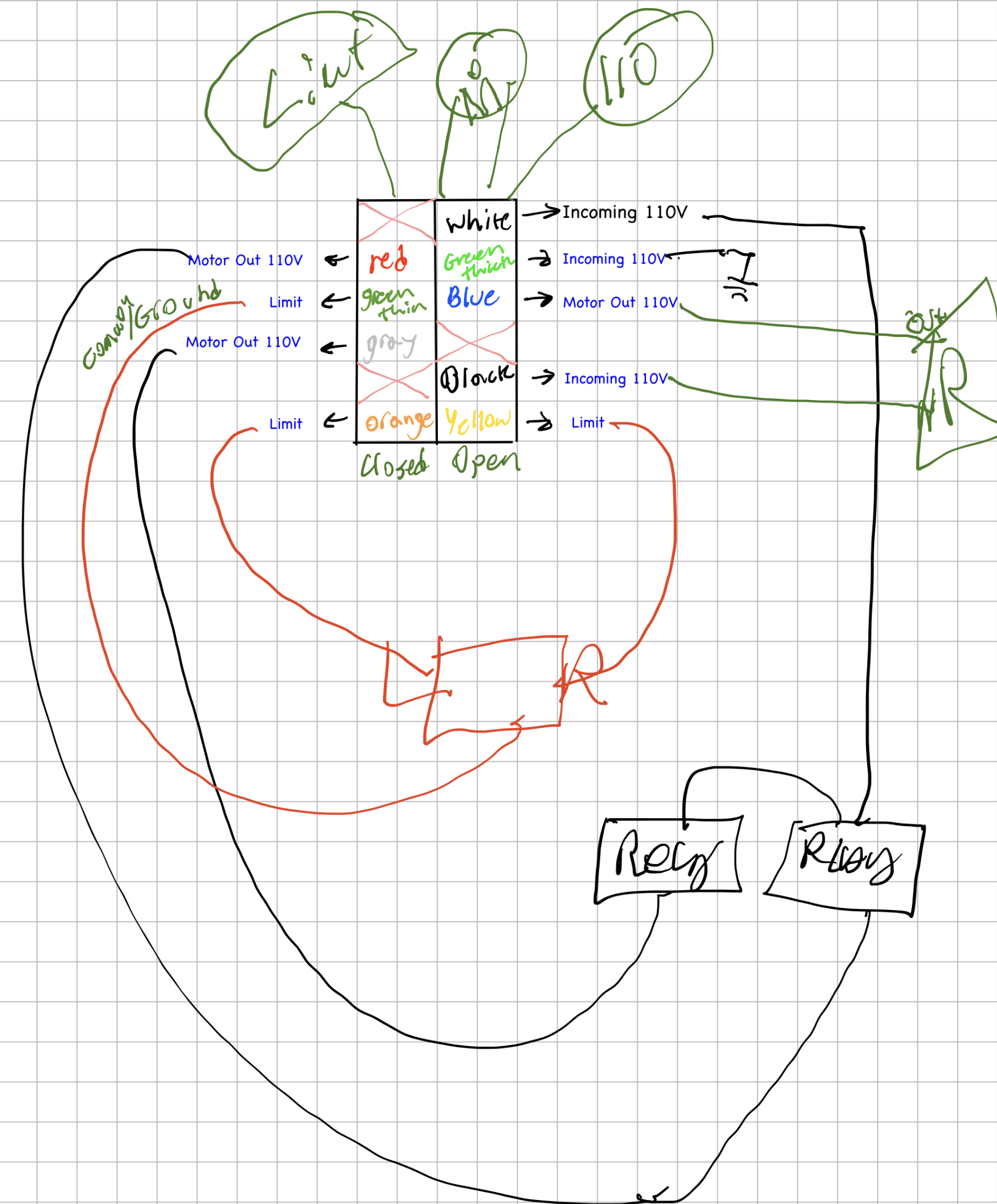
I then connected the wires from the relay board to the motor. The limit switches to the GPIO pins and a ground pin. The trigger pin to the GPIO as well, but since the voltage was 5V, I used a resistor to step it down to 1V to avoid damaging the Raspberry Pi. I found out that the safety signal required a 24V power input, which the original board provided, so I was not able to get that connected, yet. That's a future improvement that I want to make, but for now I just left it disconnected and made sure that my code could handle it being disconnected for now.
Conclusion
After everything was installed, I tested it out and it worked perfectly! I was able to open and close the gate using Home Assistant, and I could see the state of the gate in real-time on the dashboard. The actual physical buttons were actually more impressive to me as I am not a hardware person, so being able to wire up the Raspberry Pi to the existing motor and limit switches and have it work was a really rewarding experience. I learned a lot about electronics, programming, and home automation throughout this project, and it was honestly It was a great feeling to have built something like this from scratch, and it was a fun project that taught me a lot about electronics, programming, and home automation.
Notes
I do not recommend doing a project like this, as it can be dangerous if you don't know what you're doing, but if you have the skills and knowledge to do it safely, then I highly recommend it as a fun and rewarding project.
Also using a Raspberry Pi for a project like this is overkill and has the potential to break soon due to the SD card wearing out. A more robust solution would be to use a microcontroller like an ESP32, but I used a Raspberry Pi for this project because I had it, I wasn't using it and the relays are simply a HAT on-top of the GPIO pins, so it was the easiest solution to get up and running quickly. As during this entire project the gate was still able to open using the original controller but then I would need to use a drill with a hex adapter to manually close the gate. I wanted to make sure that I had a working solution as quickly as possible, and then I could iterate on it and make it more robust in the future.
Future Improvements
- Add support for the safety signal
- Switch to a microcontroller like an ESP32 or an Arduino for a more robust solution